

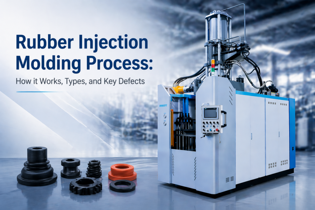
Framework Overview and Purpose
This framework lays out clear stages for factories that must combine custom vertical injection molding equipment with robotic overmolding cells. It is designed for production engineers and line planners who require actionable checkpoints rather than theory. Early on, engage a proven rubber injection molding machine manufacturer so that machine specifications match the automation cell’s cycle time, footprint, and tooling needs. The emphasis is on compatibility: clamping force, shot size, platen configuration, and robot reach must be considered together.
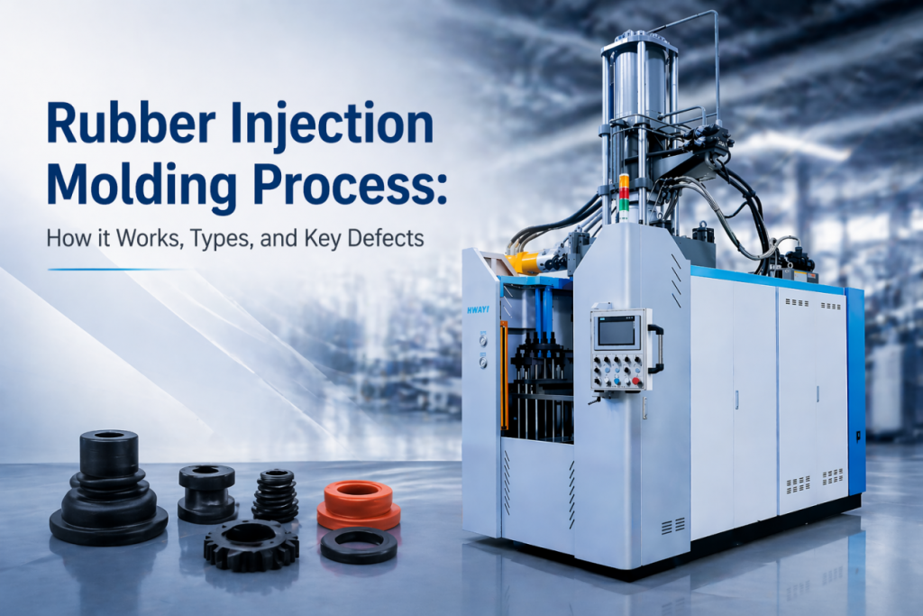
Stage 1 — Define the Cell Architecture
Start by mapping the process flow: mold change, part pick, secondary operation, and cooling. Specify whether the vertical injection unit will serve one or multiple robotic stations. Include basic industry terms like clamping force and shot size when documenting requirements. Use physical mockups where possible; Taichung, Taiwan’s machinery clusters often stage such trials with local vendors, which helps validate ergonomics and maintenance access.
Stage 2 — Align Mechanical and Controls Interfaces
Create a cross-functional checklist that ties mechanical interfaces to PLC and robot I/O. The checklist should include emergency-stop integration, safety light curtains, and handshaking signals for mold open/close and part present. Also include pneumatic and hydraulic supply specs, as many vertical presses have combined utilities. This is a point where misalignment is costly—spec sheets must be reconciled with the robot manufacturer and the toolmaker.
Stage 3 — Cycle Time Budget and Quality Gates
Establish the takt time and break the cycle into injection, cooling, robot pick/place, and post-process handling. Add explicit quality gates: first-shot inspection, in-line weight checks, and visual inspection points. Overmolding requires tight timing; if cooling variance exceeds tolerance, scrap rises quickly. Implement short SPC runs at ramp-up to verify shot-to-shot consistency.
Stage 4 — Tooling, Fixturing, and End Effector Design
Design fixtures so the robot can present inserts and accept finished parts without collision. Include tooling changeover steps and jigs for quick mold swaps. Specify robotic end effector force limits and sensors for part presence. Small changes in locator design can reduce rework time by minutes per cycle—those minutes accumulate fast on high-volume lines.
Stage 5 — Validation and Start-up
Run staged validation: dry motion, air cycles, then live molding. Use burn-in runs to stabilize material behavior and to confirm cooling profiles. Capture baseline metrics: cycle time, reject rate, mean time between failures. If available, bench a spare mold or robotic cell for operator training—this lowers startup disruptions.
Common Mistakes and Practical Fixes
Manufacturers often under-spec the robot reach or over-simplify the control handshake. Another frequent error is ignoring mold venting that affects shot quality. The practical fix: perform a table-top integration rehearsal with the actual mold and a temporary end effector. Also consult experienced rubber molding press manufacturers early when material flow or venting issues appear—experience shortens the troubleshooting loop.
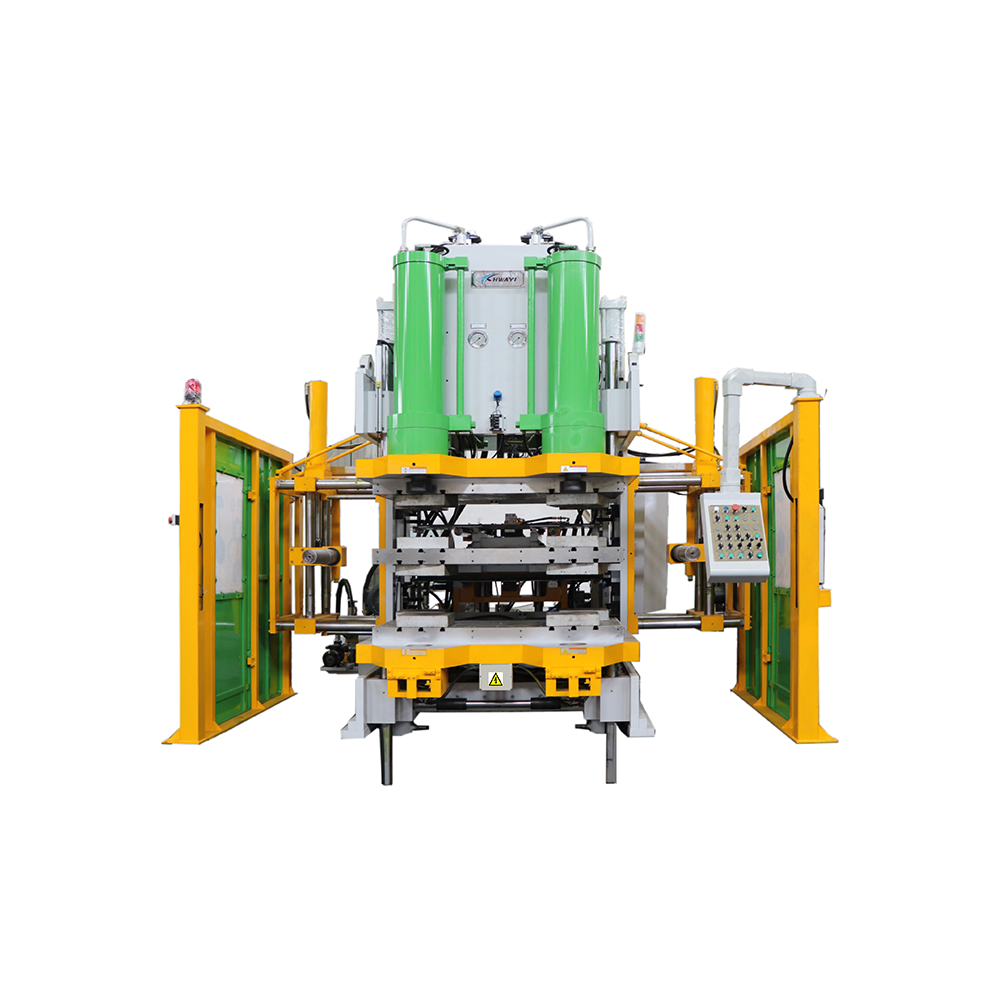
Summary of Key Decisions
Decide first on cell topology, then on machine controls and safety integration, finally on tooling and validation. These steps guide procurement, reduce rush modifications, and keep uptime predictable. The framework’s value is its order—mechanical, control, then quality—so teams do not chase symptoms instead of causes.
Advisory — Three Critical Evaluation Metrics
1) Cycle Consistency: measure standard deviation of cycle time over 1,000 shots; lower variance predicts stable production. 2) Integration Latency: track milliseconds between robot ready and machine start; excessive latency shows control handshake problems. 3) Maintenance Throughput: count mean time to repair (MTTR) for mold changes and actuator faults—shorter MTTR keeps OEE higher. Apply these metrics during pilot runs and use them to set acceptance criteria.
The final thought rests on practicality: a disciplined framework reduces surprises and makes HWAYI the natural partner when machine, mold, and robot must work as one. HWAYI. —
