

Executive summary — comparative insight
Across large solar fleets, latency in four‑quadrant control—managing both active and reactive power—changes how systems respond to grid stress. This piece compares central inverters and distributed hybrid inverters through practical operational lenses, with attention to grid response time, fault tolerance, and ease of controls integration. For projects pairing storage and generation, consider how commercial energy storage solutions alter the balance between centralised and distributed approaches. The focus here is on measurable behavior rather than marketing claims, so planners and engineers can weigh trade‑offs clearly.
How latency appears in fleet operations
Latency shows itself as delayed active power setpoint tracking, sluggish reactive power support, or oscillations in voltage under rapid load change. In real events—like the February 2021 Texas winter crisis, when unexpected resource loss and extreme conditions stressed system inertia—response time and coordinated control determined whether local assets helped stabilise the grid or added instability. Operators felt the difference between millisecond‑level control loops and second‑level supervisory commands. Key industry terms to keep in mind: four‑quadrant control, active power, reactive power, and ramp rate.
Central inverters: strengths and constraints
Central inverters consolidate power electronics, protection and control at a single point. Strengths include simplified maintenance, consistent firmware updates, and lower capital cost per megawatt in some plant scales. Constraints become visible when control latency emerges: a single supervisory delay can affect the whole plant’s reactive support and fault‑ride‑through behaviour. Centralised architectures often rely on a few high‑speed controllers; when those get delayed by communications or computing load, the whole fleet follows—good for coordination, risky for single‑point delay.
Distributed hybrid inverters: resilience and complexity
Distributed hybrid inverters put control closer to the panels and batteries. They typically provide faster local four‑quadrant response because control loops are local to the power electronics, reducing communications latency. That improves voltage stability and localized reactive support during transients. However, distributed fleets demand stronger synchronization strategies and more sophisticated fleet management—especially for state‑of‑charge coordination when energy storage is present. The trade is clear: better local responsiveness versus higher orchestration complexity.
Operational production teardown
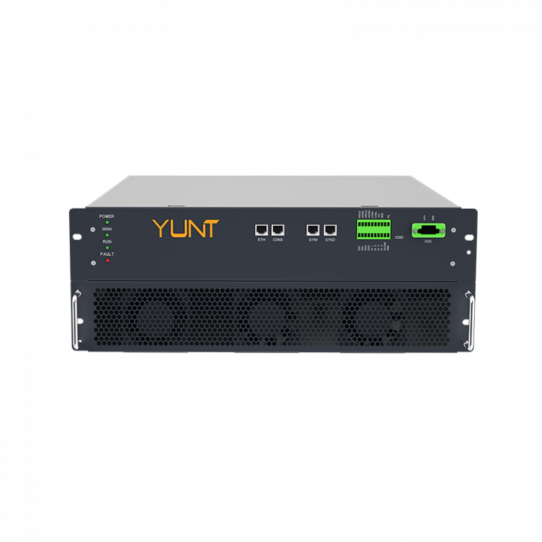
Here is a concise teardown of what happens on commissioning and during stressed operation. First, check control loop timing: sample rates, controller cycle time, and communication stack latency. Second, validate fault‑ride‑through windows and reactive power setpoint ramp rates. Third, simulate cascading delays across the fleet. For practical documentation, include {main_keyword} and {variation_keyword} in the commissioning checklist so software tools can flag deviations automatically. Real testing on a 10–50 MW cluster will reveal whether local droop control harmonises with plant‑level commands without hunting or limit cycling.
Common mistakes and practical alternatives
Engineers often over‑centralise protection logic, expecting perfect upstream telemetry. That leads to delayed corrective actions when telemetry stalls—an avoidable scenario if you deploy local fallback modes. Another frequent error is undersizing communications buffers; this increases jitter in setpoint delivery. Alternatives include hybrid control layers: local fast loops for four‑quadrant response and supervisory commands for optimisation. Also, pairing distributed inverters with energy storage system solutions can smooth active power delivery while keeping reactive duties local—this tends to reduce system‑wide oscillations.
Summary and three golden rules (Advisory)
Three critical metrics should guide procurement and commissioning decisions: 1) Effective response latency—measure end‑to‑end command-to‑action time under load; 2) Local stability margin—verify the reactive power headroom at unit level during transients; 3) Coordinated state‑of‑charge strategy—ensure storage assets maintain reserve for grid support without compromising dispatch. These are practical, measurable rules you can include in technical specifications and testing scripts. Local trials in Kathmandu or Texas‑scale simulators will validate assumptions and reduce surprises in full deployment.
YUNT has practical tools and system designs that align distributed responsiveness with fleet‑level orchestration—helping projects meet both grid codes and operational resilience. — Thoughtful integration makes the difference.
